Eran Meister appointed Director of Synopsys’ Sales Center in Israel

Photo above: Eran Meister, the new Director of Synopsys Sales Center in Israel

Synopsys has announced the appointment of Eran Meister as the Director of its Sales Center in Israel and will be responsible for leading a team of 15 sales experts dedicated to the Israeli market. Eran joined Synopsys Israel in 2003 and has been instrumental in the past 20 years in promoting the adoption of the company’s software solutions among nearly 100 global R&D centers and startups in Israel specializing in semiconductors. He has managed semiconductor IP sales and has also led the design services in Israel. Prior to joining Synopsys, Meister worked at Supertech, serving for 4 years as the manager of the company’s design center.

Meister: “My team and I are committed to providing strong support to global R&D centers and startups navigating through this challenging period, particularly those currently developing new generations of chips to be launched by the end of the crisis. We will equip them with Synopsys’ new solutions, such as technologies for photonic chip design (as an alternative to silicon), 2-nanometer chip design technologies, and new design service and will offer our solutions in a SaaS model.”

Steve McDonald, Regional Vice President of Sales for Europe and the Middle East at Synopsys, stated: “Israel is a significant market for Synopsys. We are continually impressed by the level of entrepreneurship and technological innovation in Israel. Eran is the right person at the right time to lead the Israel sales center and tackle the forthcoming challenges.”

Founded in 1986, Synopsys is a global leader in electronic design automation (EDA). Today it employs over 19,000 people and generates anuual revenues of approximately $5 billion. The development, sales, and support center in Israel has been located in Herzliya Pituach since 1997. Presently, Synopsys employs 160 people in Israel and is actively recruiting more.

SmartNICs Drive Greater Efficiency in Data Centers

By: Rita Horner, Program Manager at the Solutions Group, Synopsys 

Super-fast data transfer and efficient data processing form the backbone enabling a wide array of modern applications based on hyperscale data centers. Demand for insatiable bandwidth continues unabated and Ethernet speeds have reached 400G/800G bits per second, driven in large part by hyperscalers. These high data rates take a toll on server application processors. This is where network interface cards (NICs) come in. NICs support communication between computers in a system by converting data packages to signals that are spread throughout a network.

Thanks to their programmability and hardware acceleration capabilities, SmartNICs bring flexibility and efficiency to data center networking, storage, and security. By offloading various routine tasks, SmartNICs free host server CPUs to focus on core application processing functions. This article, originally published in the “From Silicon to Software” blog, examines how SmartNICs are supporting our increasingly digital world, emerging data center infrastructure trends, and electronic design automation (EDA) and IP technologies that can help you keep up with the evolution.

Understanding the Intelligence of SmartNICs

As network speeds increased from 1G to 10G to 112G SerDes and Ethernet speeds from 25G to 100G to 200G/400G and, now, 800G, the thinking about hardware architecture has shifted. A peek inside a traditional data center architecture would reveal CPUs, memory, storage, and network components. In recent years, a consensus has formed around the thought that general-purpose CPUs are no longer the best place to run infrastructure functions. A lot of overhead is required to support functions like hypervisors, routing, and load balancing, as well as IO-intensive security functions like deep packet inspection and data storage encryption/decryption.

Some hyperscalers have estimated that around half of CPU cycles are consumed by non-revenue-generating infrastructure tasks. SmartNICs can take on much of the heavy lifting, freeing CPUs to focus on revenue-generating application processing. The intelligence of SmartNICs comes from their programmability, along with their hardware acceleration capabilities. Bringing together wired networking and computational resources on a single card, SmartNICs feature their own on-board processor, accelerators with a custom ASIC implementation, or an FPGA and high-speed memory and IOs.

Integrating intelligence into these networking components has evolved to accommodate changes in data center bandwidth requirements. Initially, there was a focus on offloading infrastructure functions away from the host server CPU. Then, platform functions like cloud technologies were offloaded, from hypervisors to virtual machines, containers, and then microservices. Now, we’re seeing demands for application acceleration; for example, the speeding up of tasks such as video transcoding, encryption/decryption, and packet processing. CPUs can’t support the packet processing demands at today’s highest line rates, so offloading to programmable hardware, in the form of SmartNICs, makes sense.

Data Center Infrastructure Trends

With many potential use cases, what’s the right mix of components for a SmartNIC? Well, there really isn’t a one-size-fits-all approach. Data processing units are at the heart of SmartNICs, and can contain components for programmable compute, network protocol management, security, and storage. For some data centers, a few processor cores are perfect because they’re mainly used for virtual machine management. For others, more than a dozen processor cores are needed to run, say, an entire Linux operating system instance. Looking ahead, here are a few data center infrastructure trends to consider to ensure that your SmartNICs will serve you well into the future as networking traffic continues to grow:

  • The infrastructure of the future for SmartNICs is a disaggregated one, based on four types of die or chiplets: a CPU subsystem, IO subsystem, accelerator ASIC, or FPGA and optionally integrated memory, such as high-bandwidth memory (HBM). Disaggregated dies, or chiplets, support power and area goals while providing the flexibility and product modularity to address different needs in a single package. By comparison, a monolithic approach results in a large, complex chip that comes with yield and time-to-market risks as well as high costs.
  • In a disaggregated die approach, high-speed connectivity between the components is essential to ensure smooth and fast data transfer. High bandwidth, power efficiency, and low latency are key criteria to meet. Universal Chiplet Interconnect Express (UCIe) is emerging as an answer.
  • For main deployment of SmartNICs in every server, the hardware needs to be integrated seamlessly in an open-standard software stack and should be able to run an open network operating system (NOS). Ideally, infrastructure functions are deployed as pre-built containers with APIs that plug into the rest of the software stack layers.

Data center architectures are continuing to evolve to meet ever-increasing bandwidth demands. As such, reliability, security, and interoperability of their IP blocks remain critical for SmartNICs, given their important role in the smooth flow of data traffic. This is where Synopsys can help, with our comprehensive portfolio of advanced IP at different process nodes along with our broad array of multi-die design and verification solutions.

On the IP side, we offer:

  • Die-to-die interfaces including 112G XSR PHY and controllers
  • ARC processors for networking applications
  • Foundation IP including low-latency embedded memories with standard and ultra-low leakage logic libraries
  • Memory interfaces including DDR and HBM PHYs and Controllers
  • Standards-based security IP including hardware secure modules with root of trust, interface security modules, cryptography, and security protocol accelerators
  • Accelerators including DSP
  • Cache coherent expansion including CCIX/CXL controllers, inline AES cryptography, and PCI Express® PHY and Controller
  • Network interfaces including Ethernet Controllers and PHYs for speeds up to 800G.

On the design and verification side, we offer technologies to accelerate the development of multi-die designs, such as our comprehensive and integrated 3DIC solution, which encompasses architectural planning, silicon engineering, 3D system design, verification, test, co-packaged optics, silicon lifecycle management, signoff/system analysis, and IP. In addition, our virtual prototyping tools can help you determine parameters such as the right mix of processor cores and the ideal accelerator for your design. We have design services support, too, to assist with SmartNIC design and/or IP integration and verification.

Summary

Our digital world revolves around high volumes of complex data. To ensure an array of swift and seamless transactions online and in the cloud, data center architectures are moving to a composable model, where homogeneous networking, storage, and compute resources are connected via pluggable optical modules (and co-packaged optics merging electronic and photonic components in the future). In this environment, SmartNICs take the load off of primary compute resources, allowing them to focus on core application processing. While NICs have been around since the mid-1980s, their increased intelligence has made them indispensable for today’s hyperscale data centers. Successful mainstream deployment depends on integration of multi-vendor hardware into industry-standard, open-source software stacks.

Synopsys Prepares for the Growth of Multi-chip Market

Above: John Koeter. “We are jointly investing and cooperating with ARM, our competitor in other IP sectors”

Synopsys believes that deep change is underway in the chip industry, which will speed up the migration to large chips built from a wide range of chiplets – connected silicon dies – that are incorporated in the package. Synopsys’  Solution Group Senior VP for Marketing and Strategy, John Koeter, told Techtime that as part of this assessment, Synopsys is strengthening the cooperation with its competitor ARM, in the area of IP (Intellectual Property) for processors, and is developing new die-to-die interconnect modules.

The Solution Group is in effect  Synopsys’ intellectual property and Design Services group. Although the company does not publish sales data by sector, a report by IPNest indicates that Synopsys’ IP sales totaled $1.076 billion in 2021, almost 20% of the estimated $5.5 billion global market. “We feel that the trend separating monolithic ASIC components into different chips in the form of chiplets is strengthening,” Koeter said.

“Today, it is possible to integrate very large silicon components with an area of 800 sq.mm., but it is very hard. Studies show that there will soon be a need for components with an area larger than 3,000 sq.mm., which is why there is no alternative to the chiplet-based approach. The industry is going in the direction that Intel showed in the Ponte Vecchio GPU for High Performance Computing (HPC), which contains 63 chiplets on a single chip.”

The Main Challenge: Die-to-Die Interconnect

“The migration to multi-die systems-on-a-chip (SoCs) has many benefits. It is possible to offer more functionalities on the processor; for example, to integrate a communications module made with a 10-nanometer process node with processors built by 5-nanometer and 3-nanometer processes. This approach lowers costs, enables the use of proven modules, improves performance, and lowers development costs by about 30%. Gartner estimates that this market will grow to around $50 billion in 2024.

John Koeter and Ehud Loewenstein (Israel Sales Director) with Habana Labs' Thank you Trophy
John Koeter and Ehud Loewenstein (Israel Sales Director) with Habana Labs’ Thank you Trophy

“These systems require fast die-to-die interconnect. This is a sector in which we are jointly investing and cooperating with ARM, our competitor in other IP sectors. We believe that the chiplet interconnectivity market (D2D I/O) will be a very large market for us, and we are now working on developing new solutions for it. The objective is to provide a complete array of D2D I/O solutions, such as communications interfaces, memory access interfaces, and more.”

What are the other major trends that you see in the market?

“We are currently the second largest IP provider in the industry, after ARM, but Synopsys has a more diverse portfolio. At any given moment, we have information on 500-600 different SoC development projects going on. On the basis of this information, we estimate that 47% of projects will yield processors made in 7-nanonmeter and smaller process technologies. The demand for manufacturing in a 5-nanometer technology is on the rise. Moore’s Law is still alive but reaching its economic limits. Another strong sector is the automotive industry, especially ADAS systems. There are a lot of 5-nanometer projects that will soon reach the automotive industry.

“However, the highest-growth sector that we identify is data centers. There is huge growth in the scope of developments in everything related to data centers: servers, storage solutions, communications cards, and so forth. We see a great many projects in edge processing and the emerging of edge data centers, with the objective of shortening latency times. This is an important sector, which is why we are also developing dedicated IP solutions to shorten latency times.”

What is the aim of your visit in Israel?

“I come to Israel at least twice a year. This time, I visited R&D centers of multinationals and also met with startups. There are so many customers and so much innovation here that, on every visit, I get new insights on the industry’s main directions. As a marketing professional responsible for strategy, it’s important for me to know these trends.”

The Continued Importance of Unified Power Format

By: Nikhil Amin and Harsha Vardhan, Verification Group, Synopsys

As chip design sizes increase, so does the total power consumption driving its operations. To meet with the increasing intelligence and power-management flow required by modern applications, system on chip (SoC) designers and verification engineers need comprehensive solutions that leverage low-power design techniques to enable fine-grained power management. Over the years, the Unified Power Format (UPF) standard, intended for specifying and verifying power intent of integrated circuit (IC) designs, has advanced and created a wide range of opportunities.

However, for low-power cells like hard macro, RAM cell, or PAD, the connectivity of low-power control signals remains ambiguous. In this article, which was originally published on the “From Silicon to Software” blog, you’ll  learn about the basics of UPF, its importance in the power landscape, how to expand low-power signoff with custom mechanisms, and how to take power-managed designs to the next level.

The History of Unified Power Format (UPF)

As development teams prioritized energy efficiency and adopted low-power approaches, they found difficulties in the specification, implementation, and verification of power management structures. Prior to today’s era of standardization and automation, they didn’t have many resources to solve design problems. The nonprofit organization Accellera Systems Initiative launched UPF for the EDA industry to enable low-power design and verification.

The organization presented it to the Institute of Electrical and Electronics Engineers (IEEE), which published the UPF standard in 2007. Since IEEE’s introduction of the standard, UPF has served as a North Star for chip designers tackling low-power, energy-efficient electronic systems and SoCs. Over the last nine years, new iterations of UPF have been published to advance alongside semiconductor technology enhancements.

Using UPF in Designs

UPF outlines design power intent, specifying control signals, routing, block configuration, and more. Its backbone is the scripting language — Tool Control Language (TCL) — which enables automation for design software, providing specific recommendations to meet low-power standards. On average, development teams report more than a dozen significant challenges related to implementation, specification, and verification of structures.

With UPF, the ability to determine the intended design operation in terms of power management has proven to be effective in overcoming these challenges. Successful implementation of low-power semiconductor designs includes checking UPF descriptions and verifying UPF against the design at multiple stages in the project. Typically, low-power design involves standard control signals such as:

  • Isolation enables
  • Clocks, resets
  • Save, restore, and retain
  • Power switch enables, acknowledgement

UPF designs the standard specifications for these control signals that are distributed traditionally through a power management unit. The most common issues that design teams encounter with low-power signals include complex logic connectivity, incorrect buffers, retimed flops for high fanout net handling, blocked control paths, and swapped connections. A UPF file specifies several key attributes for a low-power design, including:

  • Power supplies: supply nets, supply sets, power states
  • Power control: power switches
  • Level shifters and isolation cells
  • Memory retention strategies and supply set power states
  • Power states and transitions
  • Power/ground pin type

As SoC designs evolve and include more logic functions to meet advanced requirements, the use of complex macros and memories are becoming more common. These cells can have their own low-power modes and functionality which adds unique complexities to the design flow, since the primitive connectivity specifications within UPF are insufficient to meet the verification requirements and architectural-level specifications.

Expanding Low-Power Signoff: UPF and Beyond

Typically, once the initial steps for low-power design are conducted — selection of low-power components, system simulations, UPF, and register transfer level (RTL) coding — designers move to the verification phase, which requires a comprehensive toolkit with several capabilities. The initial step is static power verification and exploration, ensuring the inputs to the design flow (RTL, UPF, and SDC) are structurally and syntactically correct.

Designers need to conduct Lint and CDC checks to make sure the RTL is clean. UPF and SDC checks can be then conducted concurrently with the RTL checks — but a tool that can run these checks and perform power analysis to ensure the design functions properly is key. Software-driven power analysis comes next. For emulation-based low power flows, it is important for chip designers to ensure that peak windows for the design’s power profile are used and leveraged to generate waveforms that estimate power.

The power implementation phase includes several steps for power estimation, logic synthesis, and generating a netlist. Once the checks are complete, the final physical components are placed and routed. During the final step – signoff – designers must ensure that the connections and changes made to the netlist and UPF are consistent and clean, and the power intent is preserved.

Over the years, UPF has grown by incorporating several advanced capabilities. These range from power-intent specification process simplification to power-management flow alignment requirements of IP-based SoC designs. Verification of low power control signals by leveraging control signal connectivity of typical low-power cells such as isolation, retention, and coarse grain power switch within UPF.

Open Issues in UPF

However, for certain low-power cells, such as hard RAM and hard macro, the connectivity of low-power control signals is unclear. This makes verification a complex and manual process often leading to costly bug escapes. Simulation can identify some of these issues but is contingent on a robust simulation environment and corresponding debug capabilities. It also occurs very late in the verification cycle increasing the cost of the verification.

Cases where UPF does not have a way to define specification:

  • While UPF is extensive, the control signal connectivity for low-power cells such as RAM and hard macros remains undefined. Chips are often designed with several RAM cells, and their architecture within the chip is critical to define memory controls and enable low-power optimization features such as sleep and retention enablers. During the design process, engineers frequently rely on simulation to find connectivity issues and other power-related bugs. However, simulations take days and are typically time-intensive procedures.
  • Hard macros present a similar problem. They are often several blocks built into the chip’s design and internally isolated. UPF doesn’t provide checks for internal isolation control or polarity for internally isolated pins.
  • In addition, it is also important to verify an IP-level control signal’s connectivity to the correct SoC signal when the IP is integrated into the SoC to ensure accurate verification at the SoC level. Currently, UPF does not have a mechanism to define the specification for this connectivity.
  • Power state table (PST) dependent isolation enable checks is another area where the Low Power Architect usually defines how the isolation enable signal and its sense are related to a supply. If isolation enable becomes active or inactive in the wrong power state table, then it can propagate corruption or clamp value towards power-on logic and that may not be intended in a PST.

To support the increasing demands of advanced power management from many of today’s electronic products, it is critical to have a comprehensive low-power verification tool that validates the final design functions accurately and can accomplish all of the phases for UPF and RTL checks, power analysis, and signoff. For more information on UPF and pre-empting low-power issues, watch this webinar.

Tackling the Power Monster with UPF Checks Throughout the Design Process

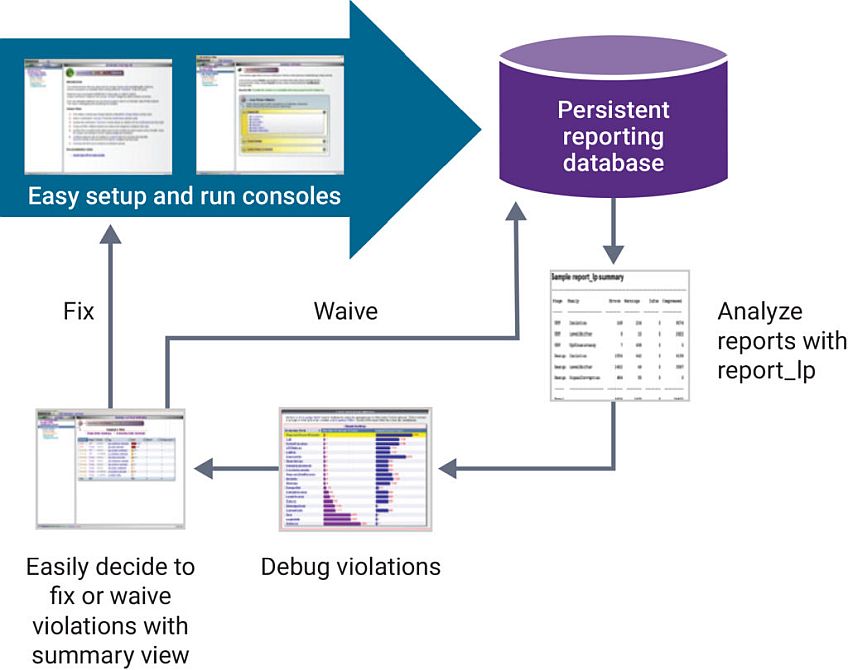
Given the nature of low-power design architectures and behavior, verification and signoff for low-power designs have become more challenging compared to always-on designs. As you’re evaluating verification technologies, consider solutions that are capable of extensive, low-noise reporting, filtering, and waiving to help simplify and also expedite complex, low-power verification signoff flows. Equipped to fully analyze chip performance and capabilities, you can be in a solid position to find and solve low-power bugs faster.

To address the RAM cells, a solution that allows you to quickly conduct full connectivity checks and identify potential problems can mitigate resource costs. As for the hard macros, a solution that allows you to specify control and polarity for these internal components can address the associated challenges.

The Synopsys VC LP™ static low-power verification solution enables all UPF checks, such as scans for power intent consistency, architecture at RTL, structural and power and ground (PG), and functionality. VC LP is a multi-voltage low-power static rule checker that allows developers to validate UPF low-power design intent quickly and accurately. It also features hierarchical power state analysis, power state table debug, and Synopsys Verdi® debug. VC LP also provides solutions for hard macro and RAM cells that UPF doesn’t include.

The platform includes over 650 checks — covering electrical and architectural evaluations — and offers full-chip performance and capacity for comprehensive signoff. It allows users to conduct checks at every step of the chip design process from register-transfer-level (RTL) to post-synthesis and post-place-and-route PG netlist. VC LP offers predictive checks for designers to identify potential implementation problems, allowing for discovery and remediation earlier in the process, as well as providing support for multiple hierarchal flows, such as Black Box and Extracted Timing Models (ETM).

As low-power design continues to become an increasingly important priority and more devices connect to the internet, chip developers will have to keep pace with demand. Design teams will need to prioritize low-power designs and employ advanced power management techniques to operate across all power states going forward.

University Program Nurtures Next Generation of Engineers

By Patrick Haspel, Global Program Director, Academic Partnerships and University Programs, Synopsys

The COVID-19 pandemic has accelerated our digital migration, moving more of our activities online. Ajit Manocha, president and CEO of SEMI, has discussed how critical it will be for the industry to close the talent gap. Investing in science, technology, engineering, and math (STEM) education is one way to nurture the interests and skillsets that are needed to bring more engineers into the workforce.

Collaborative business/university relationships, where businesses provide resources that complement or augment educational programs, provide a nice bridge between the two worlds. One such example is the Synopsys Electronic Design University Program, which provides academic and research institutions with access to electronic design automation (EDA) software, technical support, curriculum, and more.

The university bundle consists of more than 200 tools for a nominal fee and licensing agreement in support of fundamental research and education efforts. In this article, which was originally published on the From Silicon to Software blog, I’ll highlight some key examples that illustrate the mutually beneficial outcomes that are resulting from close collaboration between the business and academic worlds.

VLSI Training Course at Tel Aviv University

Creating the next generation of chip design engineers needs to start at the university level. Consider a project involving a complex 5nm design, which would require a team for implementation, verification, software design, and more. Such an endeavor could involve more than 100 people who have the latest skills. However, it’s not always easy to find the right mix of engineers.

Israel, for example, is in a region of the world where the dearth of electronic design talent is extremely high. To help create a pipeline of engineers, Zvi Webb, a retired applications engineering director from Synopsys, is serving as VLSI lab manager at Tel Aviv University and is developing an introductory very large-scale integration (VLSI) course based on the latest chip design tools. Students there, Webb noted, hadn’t been exposed to a digital design workflow and tool chain. Instead, they were building their designs manually.

Webb’s course will be offered in the spring of 2022 and will cover topics such as Verilog, logic synthesis, static timing analysis, and placement and routing, providing students with real-world expertise that can help open doors once they’re ready for the workforce. The training outline was derived from material prepared by Professor Adam Teman from Bar Ilan University. “The new course will bring student engineers more knowledge – they will gain an understanding of what VLSI means, what the steps are, how to perform checks,” Webb said.

NC State University Creates PDK for Physical Verification at 3nm

What constitutes an effective 3nm node? According to research conducted by the Electrical & Computer Engineering Department at North Carolina State University, which based its examinations on several IMEC papers, the 3nm node is marked by a gate length of approximately 15nm, cell track height of 5.5T, and contacted poly pitch of 42nm. Scaling has been enabled by design technology co-optimization to achieve the desired benefits; however, as Moore’s Law slows down, it’s now also important to look at system technology co-optimization, examining ways to reengineer the power grid and utilize new device structures (such as gate all-around FETs).

Dr. Rhett Davis, a professor at the university’s Electrical & Computer Engineering Department, has teamed up with graduate students, other faculty, and the Synopsys University Program to create an open-source 3nm process design kit (PDK) for education and industry research. Specifically, the team wanted to explore the impact of new structures like gate all-around FETs and scaling boosters like buried power rails and 5.5T height metal pitch.

A cross-section of a single transistor in the FreePDK3's vision of a 3nm process (front and side views)
A cross-section of a single transistor in the FreePDK3’s vision of a 3nm process (front and side views)

“What we found when making this kit is that transistors aren’t really shrinking anymore. Instead, they’re getting taller. That is, foundries are finding economical ways to stack them. Our kit compiles the best available public data into a set of rules that show us how to work with this new technology,” explained Davis.

To create the resulting FreePDK3, the team used Synopsys IC Validator for physical verification, Synopsys Custom Compiler for layout and schematic entry, Synopsys StarRC for parasitic extraction, and HSPICE® technology for circuit simulation. The FreePDK3 is published on the GitHub repository.

Engaging the Next Generation of Engineers

These examples illustrate the work that academia is engaging in with the business world. Through our Electronic Design University Program, Synopsys provides full-semester coursework for undergraduate and graduate programs in IC design and EDA development; teaching resources such as libraries and PDKs, and technical support and training. In addition, Synopsys also offers academic programs in the areas of optical design and static analysis software.

The Synopsys Foundation is committed to advancing STEM education opportunities that contribute to the growth and development of our future technology leaders. Through close collaboration, businesses and universities can help nurture the next generation of engineers for semiconductor and electronics industries that are continuing to embark on new innovations that are fueling our smart, connected world.

Optimizing PPA for 3DICs Requires a New Approach

By Raja Tabet, Sr. VP of Engineering, and Anand Thiruvengadam, Product Marketing Director, Custom Design and Physical Verification Group

Sponsored by Synopsys.

The adoption of 3DIC architectures is enjoying a surge in popularity as product developers look to their inherent advantages in performance, cost, and the ability to combine heterogeneous technologies and nodes into a single package. As designers struggle to find ways to scale with complexity and density limitations of traditional flat IC architectures, 3D integration offers an opportunity to continue functional diversity and performance improvements, while meeting form-factor constraints and cost.

3D structures offer a variety of specific benefits. For example, performance is often dominated by the time and power needed to access memory. With 3D integration, memory and logic can be integrated into a single 3D stack. This approach dramatically increases the width of memory busses through fine-pitch interconnects, while decreasing the propagation delay through the shorter interconnect line. Such connections can lead to memory access bandwidth of tens of Tbps for 3D designs, as compared with hundreds of Gbps bandwidth in leading 2D designs.

From a cost perspective, a large system with different parts has various sweet spots in terms of silicon implementation. Rather than having the entire chip at the most complex and/or expensive technology node, heterogeneous integration allows the use of the ‘right’ node for different parts of the system, e.g., advanced/expensive nodes for only the critical parts of the system and less expensive nodes for the less critical parts.

In this post, which was originally published on the “From Silicon to Software” blog, we’ll look at 3DIC’s ability to leverage designs from heterogenous nodes– and the opportunities and challenges of a single 3D design approach to achieve optimal Power, Performance, and Area (PPA).

Vertical Dimension Changes the Design Strategy

While 3D architectures elevate workflow efficiency and efficacy, 3DIC design does introduce new challenges. Because of the distinct physical characteristics of 3D design and stacking, traditional tools and methodologies are not sufficient to solve these limitations and require a more integrated approach. In addition, there is a need to look at the system in a much more holistic way, compared to a typical flat 2D design. Simply thinking about stacking 2D chips on top of each other is insufficient in dealing with the issues related to true 3D design and packaging.

Since the designs must be considered in three dimensions, as opposed to the typical x, y aspects of a flat 2D design, everything must be managed with the addition of the z dimension  – from architectural design to logic verification and route connection – including bumps and through-silicon vias (TSVs), thermal, and power delivery network (PDN) opportunities for new tradeoffs (such as interposer based versus 3D stacks, memory on logic or logic on memory, and hybrid bonding versus bumps). Optimization of the ‘holy grail’ of PPA is still a critical guiding factor; however, with 3DICs, it now becomes cubic millimeter optimization, because it’s not just in two directions, but also the vertical dimension that must be considered in all tradeoff decisions.

The need for Co-design Methodology

Further complicating matters, higher levels of integration available with 3DICs obsolete traditional board and package manual-level techniques such as bump layout and custom layout for high-speed interconnects, which cause additional bottlenecks. Most importantly, interdependency of previously distinct disciplines now needs to be considered in a co-design methodology (both people and tools), across all stages of chip design, package, architecture, implementation, and system analysis.

Let’s look at an example of a specific design challenge – the goal to improve memory bandwidth. Traditionally, designers would look at how to connect the memory and CPU to get the highest possible bandwidth. But with 3DICs, they need to look at both the memory and CPU together to figure out the optimal placement in the physical hierarchy, as well as how they connect, through CSVs or silicon vias, for example. While performance is critical, designers need a way to evaluate the power and thermal impact by stacking these types of elements together in different ways, introducing new levels of complexities and design options.

Taking a Silicon-First Approach

While it might seem obvious to consider a 3D architecture in a similar manner as a printed circuit board (PCB) design, 3DICs should ideally take a silicon-first approach – that is, optimize the design IP (of the entire silicon) and co-design this silicon system with the package. Within our approach to 3DICs, Synopsys is bringing key concepts and innovations of IC design into the 3DIC space. This includes looking at aspects of 3DICs such as architectural design, bringing high levels of automation to manual tasks, scaling the solution to embrace the high levels of integration from advanced packaging, and integrating signoff analysis into the design flow.

3DICs integrate the package, traditionally managed by PCB-like tools, with the chip. PCB tools  are not wired to deal with both the scale complexity and process complexity. In a typical PCB there may be 10,000 connections. But in a complex 3DIC, there are hundreds of millions of connections, introducing a whole new level of scale which is far outpacing what older, PCB-centric approaches can manage. Existing PCB tools cannot offer assistance for stacking dies, and there is no package or PCB involved. Further, PCB tools cannot look at RTL or system design decisions.

The reality is that there cannot be one single design tool for all aspects of a 3DIC (IC, interposer, package), yet there is an acute need for assembling and visualizing the complete stack. The Synopsys 3DIC Compiler does just that. It is a platform that has been built for 3DIC system integration and optimization. The solution focuses on multi-chip systems, such as chip-on-silicon interposer (2.5D), chip-on-wafer, wafer-on-wafer, chip-on-chip, and 3D SoC.

The PPA Trifecta

Typically, when you think of large complex chips, the first optimization considered is area.  SoC designers want to integrate as much functionality into the chip and deliver as high performance as possible. But then there are always the required power and thermal envelopes, particularly critical in applications such as mobile and IoT (and also high-performance computing). Implementing 3D structures enables designers to continue to add functionality to the product, without exceeding the area constraints and, at the same time, lowering silicon costs.

But a point tool approach only addresses sub-sections of the complex challenges in designing 3DICs. This creates large design feedback loops that don’t allow for convergence to an optimal solution for the best PPA per cubic mm2 in a timely manner. In a multi-die environment, the full system must be analyzed and optimized together. It isn’t enough to perform power and thermal analysis of the individual die in isolation. A more effective and efficient solution would be a unified platform that integrates system-level signal, power, and thermal analysis into a single, tightly coupled solution.

This is where 3DIC Compiler really shines–by enabling early analysis with a suite of integrated capabilities for power and thermal analysis. The solution reduces the number of iterations through its full set of automated features while providing power integrity, thermal, and noise-aware optimization. This helps designers to better understand the performance of the system and facilitate exploration around the system architecture.  And it also allows a more efficient way to understand how to stitch together various elements of the design and even connect design engineers in some ways to traditional 2D design techniques.

Ideal Platform for Achieving Optimal PPA Per Cubic mm2

Through the vertical stacking of silicon wafers into a single packaged device, 3DICs are proving their potential as a means to deliver the performance, power, and footprint required to continue to scale Moore’s law. Despite the new nuances of designing 3D architectures using an integrated design platform, the possibilities of achieving the highest performance at the lowest achievable power makes 3D architecture appealing. 3DICs are poised to become even more widespread as chip designers strive to achieve the optimum PPA per cubic mm2.

Synopsys Announced a new simulator for converged ICs

Synopsys announced the PrimeSim Continuum solution, a unified workflow for circuit simulation technologies to accelerate the creation of hyper-convergent designs. PrimeSim Continuum is built on SPICE and FastSPICE architectures – a proven GPU acceleration technology providing runtime improvements and signoff accuracy. “PrimeSim Continuum represents a revolutionary breakthrough in circuit simulation,” said Sassine Ghazi, Chief Operating Officer at Synopsys.

Today’s hyper-convergent SoCs consist of larger and faster embedded memories, analog front-end devices and complex I/O circuits that communicate at 100Gb+ data rates with the DRAM stack connected on the same piece of silicon in a system-in-package design. This results in more simulations with longer runtimes at higher accuracy. PrimeSim Continuum addresses this complexity with a unified workflow of sign-off quality simulation engines tuned for analog, mixed-signal, RF, custom digital memory designs. Synopsys said it optimizes the use of CPU and GPU resources and improve time-to-results and cost of results.

“As modern compute workloads evolve, the size and complexity of analog designs have moved beyond the capacity of traditional circuit simulators,” said Edward Lee, vice president of Mixed Signal Design at NVIDIA. “Using NVIDIA GPUs enables PrimeSim SPICE to accelerate circuit simulation, notably minimizing signoff time of analog blocks from days to hours.” The Synopsys PrimeSim Continuum solution is now available. For more information: PrimeSim Continuum.